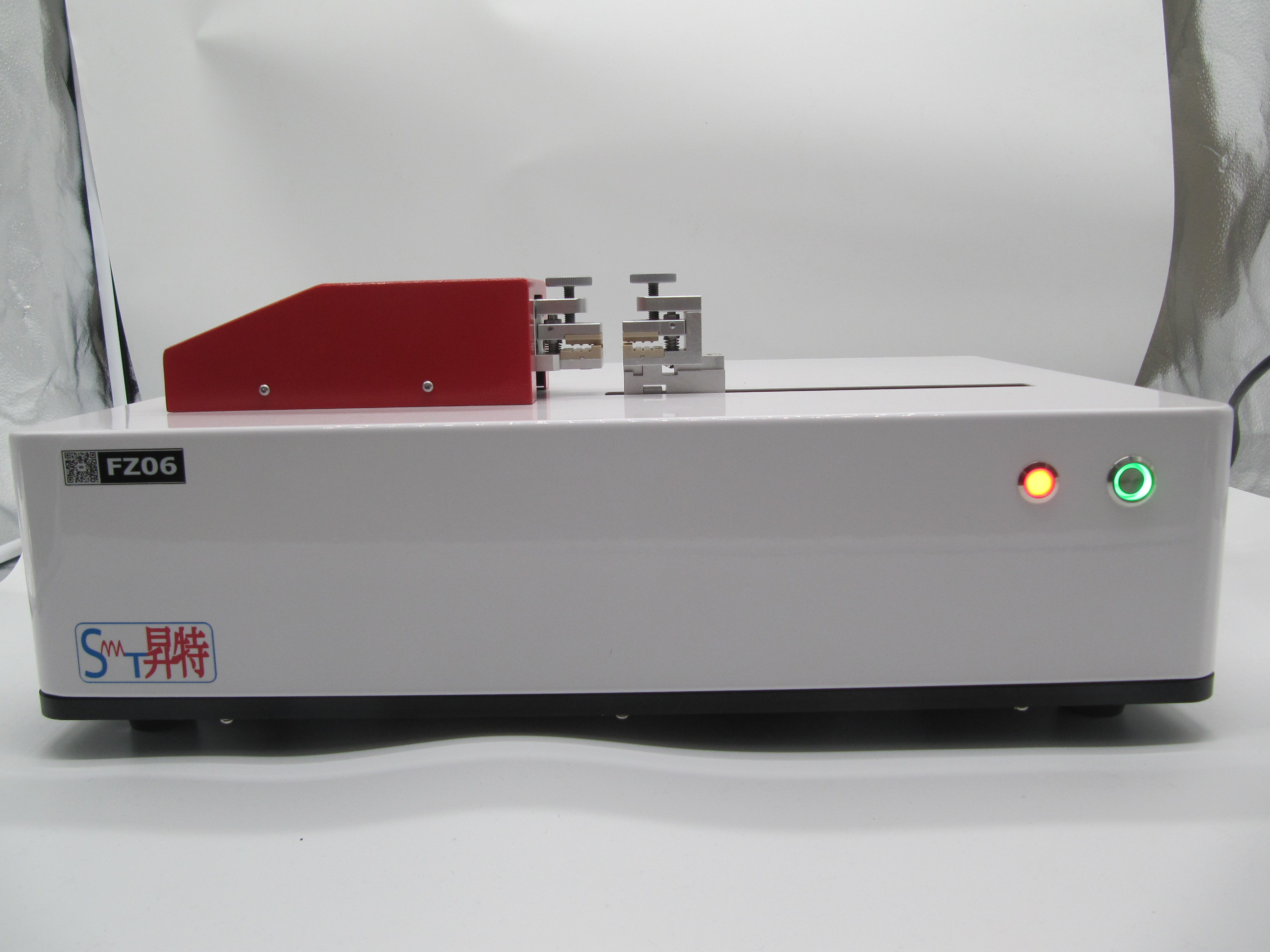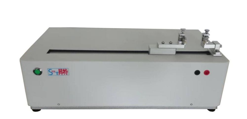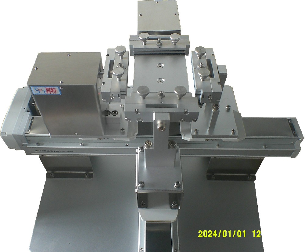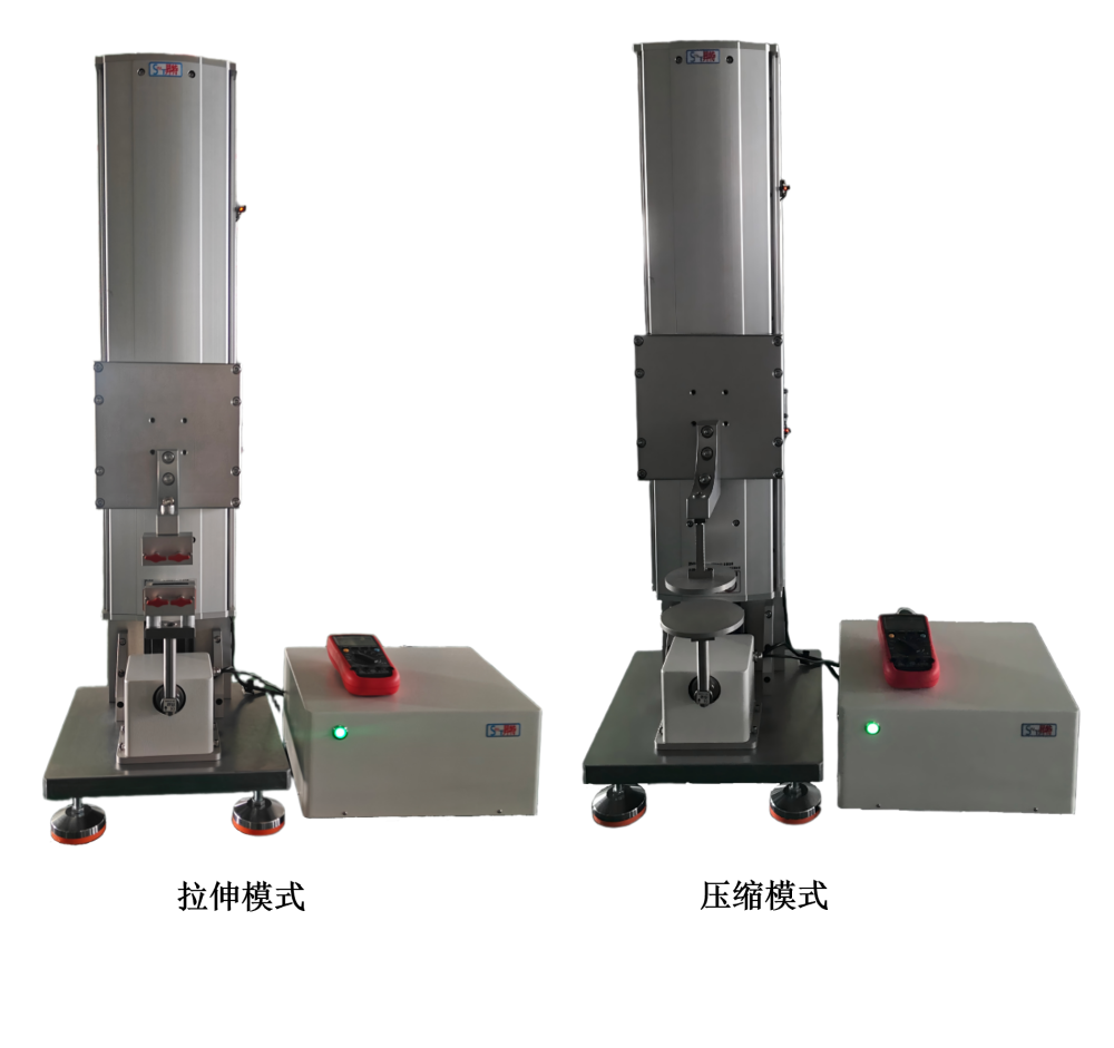

Background technology: Flexible electronic products, characterized by their soft texture and ease of bending and deformation, encompass flexible displays, flexible circuit boards, flexible batteries, flexible capacitors, etc. The market for flexible electronic products is currently in development. However, there is currently no unified flexible determination equipment and testing method for electronic products that can be bent. To address this issue, the present invention designs a bending resistance testing equipment and its testing scheme for repeatedly bending flexible electronic products, which can achieve repeated bending of flexible electronic products according to different bending radii, thereby testing the bending resistance of flexible electronic products.
Technical implementation elements: The purpose of this invention is to overcome the defects of existing technology by providing a device and method for testing the bending resistance of flexible electronic products. This device and method allow for testing with different bending radii and different bending frequencies, as well as monitoring the performance of electronic products during the bending test process, in order to solve the problem of determining the flexibility performance of existing flexible electronic products.
The present invention is implemented as follows: The invention provides a bending resistance testing device for flexible electronic products, comprising a base, an operation panel, a support frame, a fixing rod, a bending unit, and a driving unit for driving the bending unit to move in the vertical direction; the side of the base is provided with an operation panel, and the upper surface of the base is provided with a driving unit and a support frame; the support frame is internally provided with two fixing rods extending in a direction perpendicular to the upper surface of the base, the top and bottom ends of each fixing rod are respectively in sliding fit with the top and bottom of the support frame in the horizontal direction, and both fixing rods are respectively connected to both sides of the support frame through fixing rod return assist springs; the two ends of the bending unit are respectively fixed on the two fixing rods.
1. The bending unit comprises a base plate, a cylinder, a protective pad, and two fixing clamps; the two fixing clamps are respectively fixed on two fixing rods, and each of them clamps one end of the protective pad; the protective pad houses the flexible electronic product to be tested; two cylinders are symmetrically arranged on both sides of the protective pad, with the bottom of each cylinder fixed on the base plate, which is fixedly connected to the driving unit.
2. The bending unit also includes a fixed clamp gasket and a fixed knob; one end of the fixed clamp is fixed on the fixed rod, and the other end is a U-shaped slot with an opening facing the cylinder, and the end of the protective pad is located inside the U-shaped slot; the U-shaped slot is provided with a fixed clamp gasket, and the fixed clamp gasket is located above or below the protective pad; the fixed knob passes through the side wall of the U-shaped slot and presses against the fixed clamp gasket.
3. Both the top and bottom of the support frame are equipped with fixed rod slide rails, and the fixed rod is slidingly connected to the fixed rod slide rail.
4. The driving unit comprises a servo motor; the bending unit is connected to a conveyor belt, which is in turn connected to the servo motor.
5. The operation panel includes a start button, a stop button, and a touch screen for adjusting bending test parameters.
6. The top and bottom of each of the mentioned fixed rods are respectively connected to the top and bottom of the support frame near the side of the fixed rod through a fixed rod return assist spring.
7. There are four fixing clamps, which are divided into two groups. The two fixing clamps in each group clamp the two ends of the protective pad respectively; there are three cylinders, with a protective pad placed between every two adjacent cylinders.
8. The bending resistance testing device also includes an electrical performance testing mechanism, which is connected to the flexible electronic product to be tested via a connecting wire.
The present invention further provides a method for testing the bending resistance of flexible electronic products. The method comprises the following steps: Step one, according to the bending resistance testing requirements, mount cylinders of corresponding radii onto a substrate and adjust the spacing between the two cylinders to precisely accommodate the flexible electronic product to be tested and a protective pad;
Step 2: Place the flexible electronic product to be tested in the middle of the protective pad, and secure both ends of the protective pad with fixing clamps;
Step 3: Set the test speed and maximum displacement of the cylinder on the touch screen, and specify the number of bending cycles required;
Step 4: Click the start button on the operation panel, and the cylinder on the bending unit will perform an up-down displacement cycle under the control of the servo motor according to the set parameters. When the cylinder moves from the origin to the maximum displacement point, the flexible electronic product to be tested follows the corresponding radius of the cylinder to form a bend. When the cylinder moves from the maximum displacement point back to the origin, the return spring of the fixed rod pulls the fixed rod and the bending unit connected to it, so that the flexible electronic product to be tested follows the protective pad to return to a straight state;
Step 5: After setting the bending times, the bending unit automatically returns to the original point and stops operating. Loosen the fixing knob, remove the tested flexible electronic product from the protective pad, and confirm its corresponding performance after bending.
Compared with existing technologies, the present invention has the following beneficial effects: 1) The bending resistance testing device for flexible electronic products provided by the present invention can test flexible electronic products with different bending radii;
2) The bending resistance testing equipment for flexible electronic products provided by the present invention can conduct bending tests at different speeds for flexible electronic products subjected to different stresses;
3) The bending resistance testing equipment for flexible electronic products provided by the present invention can monitor other properties of the flexible electronic products while testing their bending resistance.
To illustrate the technical solutions in the embodiments of the present invention or the prior art more clearly, the accompanying drawings required for the description of the embodiments or the prior art will be briefly introduced below. It is apparent that the accompanying drawings described below are merely some embodiments of the present invention. For those skilled in the art, other drawings can be obtained based on these drawings without creative effort.
Specific Implementation Methods The technical solutions in the embodiments of the present invention will be clearly and comprehensively described below in conjunction with the accompanying drawings. Obviously, the described embodiments are merely a part of the embodiments of the present invention, not all of them. Based on the embodiments of the present invention, all other embodiments obtained by those of ordinary skill in the art without creative effort fall within the scope of protection of the present invention.
The embodiment of the present invention provides a bending resistance testing device for flexible electronic products, comprising a base 1, an operation panel 2, a support frame 3, a fixing rod 4, a bending unit 9, and a driving unit for driving the bending unit 9 to move in the vertical direction. The operation panel 2 is arranged on the side of the base 1, and the driving unit and the support frame 3 are arranged on the upper surface of the base 1. The support frame 3 is internally provided with two fixing rods 4 extending in a direction perpendicular to the upper surface of the base 1. The top and bottom ends of each fixing rod 4 are respectively slidably fitted with the top and bottom of the support frame 3 in the horizontal direction. Both fixing rods 4 are respectively connected to both sides of the support frame 3 through a fixing rod return assist spring 5. Both ends of the bending unit 9 are respectively fixed to the two fixing rods 4.
1. The bending unit 9 comprises a base plate 904, a cylinder 905, a protective pad 906, and two fixing clamps 901. The two fixing clamps 901 are respectively fixed on two fixing rods 4, and each clamp holds one end of the protective pad 906. The protective pad 906 houses a flexible electronic product 907 to be tested. Two cylinders 905 are symmetrically arranged on both sides of the protective pad 906, with the bottom of each cylinder 905 fixed on the base plate 904. The base plate 904 is fixedly connected to the driving unit. The relative positions of the cylinders 905 on the base plate 904 can be adjusted. The cylinders 905 can be replaced with different sizes according to testing needs, allowing for bending resistance tests with different bending radii. Additionally, the speed of the cylinders' up-and-down movement can be adjusted, enabling the speed to be tailored to electronic products with different stresses.
2. The bending unit 9 also includes a fixed clamp gasket 902 and a fixed knob 903; one end of the fixed clamp 901 is fixed on the fixed rod 4, and the other end is a U-shaped slot with an opening facing the cylinder 905, and the end of the protective pad 906 is located inside the U-shaped slot; the fixed clamp gasket 902 is arranged inside the U-shaped slot, and the fixed clamp gasket 902 is located above or below the protective pad 906; the fixed knob 903 passes through the side wall of the U-shaped slot and presses against the fixed clamp gasket 902.
3. Both the top and bottom of the support frame 3 are equipped with fixed rod slide rails 6, and the fixed rod 4 is slidingly connected to the fixed rod slide rail 6.
4. The driving unit includes a servo motor 7; the bending unit 9 is connected to a conveyor belt 8, which is connected to the servo motor 7. The front of the base plate 904 is equipped with a cylinder 905, and the back is connected to the conveyor belt 8; the servo motor 7 drives the conveyor belt to move up and down, thereby driving the bending unit 9 to reciprocate up and down, achieving the measurement of bending performance for multiple bending times of the flexible electronic product 907 to be tested.
5. The operation panel 2 includes a start button 202, a stop button 203, and a touch screen 201 for adjusting bending test parameters.
6. The top and bottom of each fixed rod 4 are respectively connected to the top and bottom of the support frame 3 on the side close to the fixed rod 4 through a fixed rod return assist spring 5.
The present invention also provides another embodiment, as shown in Figures 3 and 4. There are four fixing clamps 901, which are divided into two groups. Each group of two fixing clamps 901 respectively clamps the two ends of a protective pad 906. There are three cylinders 905, with a protective pad 906 sandwiched between every two adjacent cylinders 905. Using three cylinders 905 allows for the simultaneous testing of two flexible electronic products, thereby increasing the detection efficiency of the equipment.
Furthermore, as shown in Figure 4, the bending resistance testing device also includes an electrical performance testing mechanism 12, which is connected to the flexible electronic product 907 to be tested via a connecting wire 11. During the bending test, there is no relative displacement between the two ends of the flexible electronic product 907 to be tested and the fixed rod 4, allowing the electrical performance testing mechanism 12 to monitor the electrical performance during the bending process. The electrical performance testing mechanism 12 comprises a data collection unit, an electrical performance analysis unit, and an electrical performance data output unit.
The present invention further provides a method for testing the bending resistance of flexible electronic products. The method comprises the following steps: Step one, according to the bending resistance testing requirements, mount cylinders 905 of corresponding radii onto the substrate 904 and adjust the spacing between two cylinders 905 to precisely accommodate the flexible electronic product 907 to be tested and the protective pad 906;
Step 2: Place the flexible electronic product 907 to be tested in the middle of the protective pad 906, and secure both ends of the protective pad 906 with fixing clamps 901;
Step 3: Set the test speed and maximum vertical displacement of the cylinder 905 on the touch screen 201, and specify the number of bending cycles to be performed;
Step 4: Click the start button 202 on the operation panel 2, and the cylinder 905 on the bending unit 9 will perform an up-down displacement cycle under the control of the servo motor 7 according to the set parameters. When the cylinder 905 moves from the origin to the maximum displacement point, the flexible electronic product 907 to be tested follows the corresponding radius of the cylinder 905 to form a bend. When the cylinder 905 moves from the maximum displacement point back to the origin, the fixed rod return assist spring 5 pulls the fixed rod 4 and the bending unit 9 connected to it, so that the flexible electronic product 907 to be tested follows the protective pad 906 to return to a straight state;
Step 5: After setting the bending times, the bending unit 9 automatically returns to the original point and stops operating (if manual stop is required, click the stop button 202 on the operation panel). Loosen the fixing knob 903, remove the tested flexible electronic product from the protective pad 906, and confirm the corresponding performance after bending. This completes the determination of the bending resistance of the flexible electronic product.
Furthermore, during the up-and-down displacement cycle of the cylinder 905, the connecting wire 11 of the testing device 12 is connected to the flexible electronic product 907 to be tested, which is positioned between the protective pad 906, to test other performance characteristics of the flexible electronic product 907. As shown in Figure 4, if it is necessary to measure other performance characteristics simultaneously during the bending test, the connecting wire 11 of the testing device 12 can be connected to the flexible electronic product 907 to be tested, which is positioned between the protective pad 906, via the fixed rod 4 and the bending unit fixing clip 901.
The above description is merely a preferred embodiment of the present invention and is not intended to limit the invention. Any modifications, equivalent substitutions, and improvements made within the spirit and principles of the present invention should be included within the scope of protection of the present invention.